SWheg: A Wheel-Leg Transformable Robot
A tendon-driven wheel-leg transformable robot with minimalist actuator realization.
*This part serves as supplements for some information which is not included in the paper. For more detailed information, please refer to the paper at the bottom of this page.
Motivation
Wheels and Legs are two widely adopted methodologies utilized by ground locomotion platforms. The wheeled mode offers continuous ground contact and superior performance on even terrains, whereas the legged mode, with its discontinuous contact, can navigate uneven terrains effectively. Thus, a wheel–leg hybrid platform with great mobility on both flat ground (via wheels) and rough terrain (with legs) seems to be an adequate combination of a mobile platform suitable for general indoor/outdoor and flat–rough environments.
To our best knowledge, all of the existing wheel-leg transformable robots reported in the literature with N wheel-leg modules will have at least 2N actuators (driving and transformation actuator combined). However, the independent transformation control of each wheel-leg module is not a key function of the robot. So, theoretically,
1 additional actuator is sufficient to actuate the transformation of N wheel-leg modules.
Therefore, we came up with the idea to make the first wheel-leg transformable robot with minimalist actuator realization. During the literature review, another thing we noticed was that published studies on wheel-leg transformable robots are rare, especially in performance evaluations. To provide more data about general wheel-leg transformable robots and the S-shaped leg configuration, we built two platforms for more comparisons insight: Quadrupedal SWheg and Hexapod SWheg.
The Name “SWheg”: We came up with the name after the platform was fully developed. The name SWheg is short for “S-shaped Wheel-Leg”.
Experiments
Transformation Testing
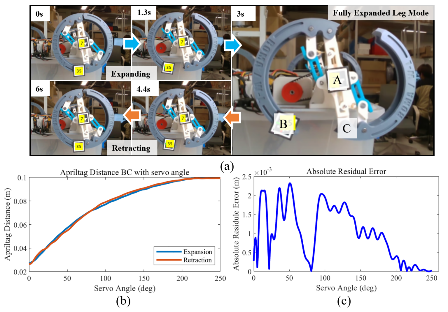
We measured the accurate mapping between the servo’s rotation angle and the module’s transformation degree, represented by the distance between BC as shown in the following picture. The rotational angle can be directly obtained from the built-in encoder of the servo. We performed 10 repetitive expanding and retracting experiments and recorded the corresponding data. The average mapping is utilized as the transformation standard and is shown in the bottom picture.

Gait Development and Field Testing
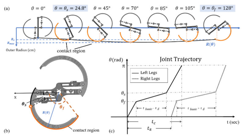
By applying phase difference to the robot, different gaits can be generated. The following table shows the phase difference of some simple gaits and the corresponding gait diagram. This control strategy can also be easily transferred to robots that have more wheel-leg modules.
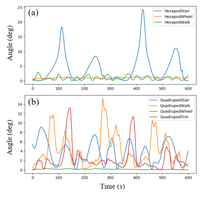
Performance (Motion Smoothness) was compared in simulation. Results are shown below, details are in our published paper. It is worth noticing that tripod gait in the hexapod SWheg platform reached significant smoothness, also validated from the IMU data. Visually it walks as if on wheels, this is another advantage of the S-shape leg morphology.


Field Testing

My Contribution
- Mechatronics Infrastructure: Finish part of electric control including electric push rods and PID control of motors based on ROS. Selection and programming of sensors including IMU and power measurement module.
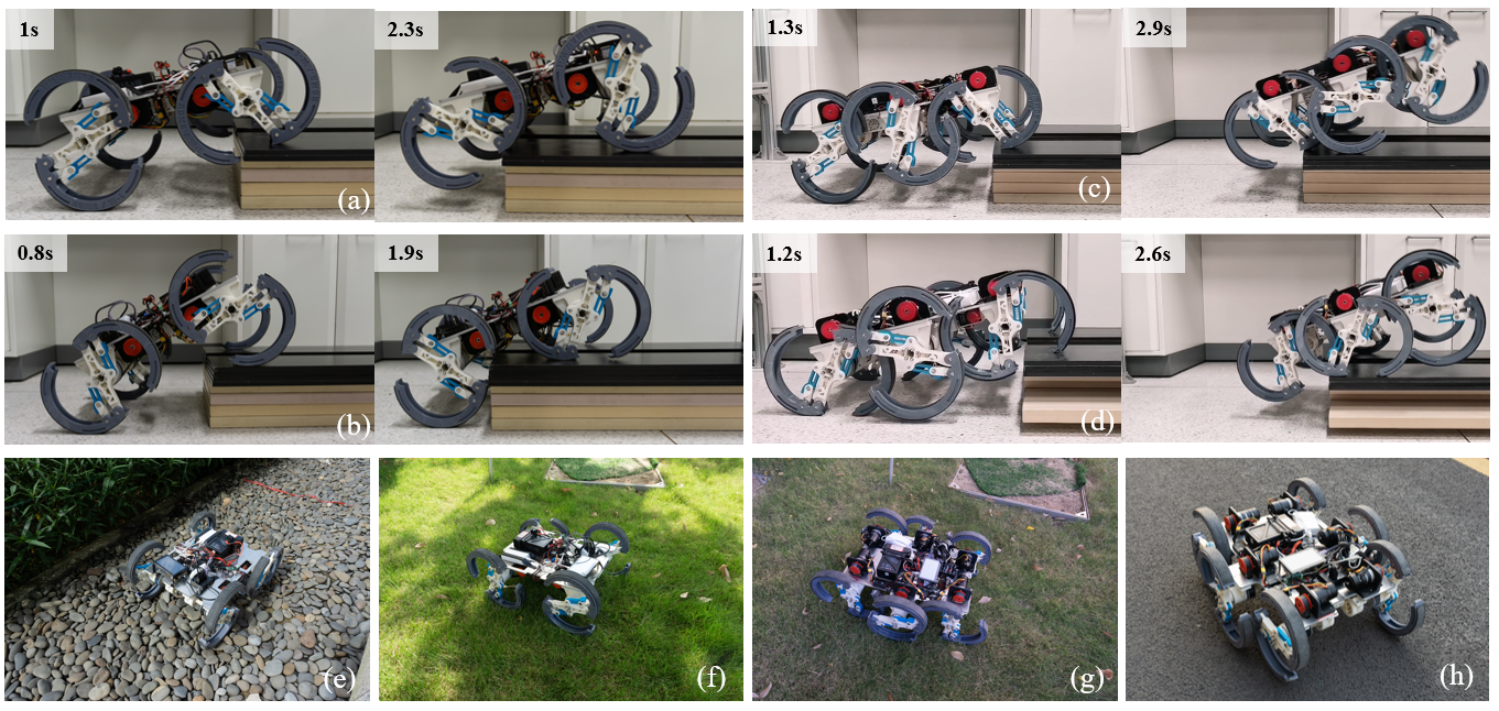
- Performance Evaluation: Finish all the field tests and data collection solely including stair climbing, motion smoothness and power efficiency experiments. Design an energy evaluation experiment and draw a strategy of movement control over multi-terrains.
- Fabrication Process: Used 3D printing, and laser cutting technology to support the processing procedure.